


Polish Films in fiber optic connectors

Polish Films in fiber optic connectors
Polishing films are essential consumables in fiber optic connector polishing processes, ensuring high-quality end-face finishes for optimal signal transmission. These films are used in the multi-step polishing process to refine and smooth the fiber end-face, minimizing insertion loss and return loss.

Types of Polishing Films for Fiber Optic Connectors
-
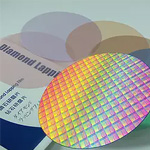
Diamond Lapping Film
- Used in the initial and intermediate polishing stages.
- Provides aggressive material removal for ceramic ferrules.
- Available in grit sizes ranging from 0.5µm to 9µm.
- Ensures precision and uniformity in fiber protrusion.
-
Silicon Carbide (SiC) Lapping Film
- Suitable for intermediate polishing.
- Works well for soft materials and epoxy removal.
- Available in various grit sizes, typically 1µm to 9µm.
-
Aluminum Oxide (AO) Polishing Film
- Used for fine polishing and achieving smooth finishes.
- Ideal for final finishing before the ultimate polishing step.
- Provides consistent, uniform polishing.
-
Silicon Dioxide (SiO₂) Final Polishing Film
- Used in the last step for ultra-fine polishing.
- Achieves high reflectivity and minimal surface defects.
- Helps to reduce scratches and improve end-face geometry.
-
MPO Flock Pile Polishing Film
- Specifically designed for MPO/MTP multi-fiber connectors.
- Helps maintain uniform pressure across the fiber array.
- Improves flatness and reduces polishing defects.

Polishing Process for Fiber Optic Connectors
-
Epoxy Removal (Using Coarse Diamond or SiC Film)
- Removes excess epoxy from the ferrule surface.
- Grit size: 9µm Diamond or SiC film.
-
Ferrule Shaping (Using Medium Diamond Film)
- Shapes the connector end-face to the desired curvature.
- Grit size: 3µm Diamond Film.
-
Pre-Polishing (Using Fine Diamond or AO Film)
- Smooths out surface imperfections.
- Grit size: 1µm Diamond or AO Film.
-
Final Polishing (Using SiO₂ Final Polishing Film)
- Achieves ultra-smooth and scratch-free fiber surfaces.
- Grit size: 0.02µm – 0.05µm.
Applications of Polishing Films
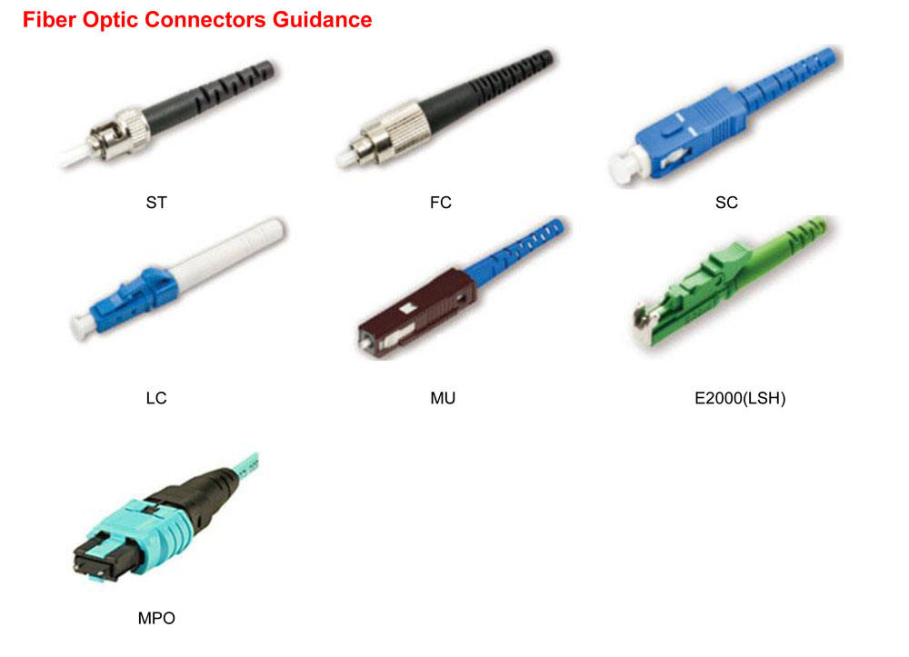
- Single Fiber Connectors (SC, FC, ST, LC, MU)
- Multi-Fiber Connectors (MPO/MTP)
- Patch Cord Manufacturing
- Field Termination Kits
- High-Speed Data Centers & Telecommunications

Key Benefits of Using High-Quality Polishing Films
- Ensures low insertion loss (IL) and high return loss (RL).
- Provides consistent polishing results with minimal defects.
- Enhances fiber end-face geometry, reducing back reflections.
- Extends connector lifespan and improves performance reliability.

SC/LC/FC/ST/MU Connector Polishing Process
Polishing fiber optic connectors such as SC, LC, FC, ST, and MU follows a structured multi-step process to achieve a high-quality end-face finish, ensuring optimal signal transmission with minimal insertion loss (IL) and high return loss (RL). Below is a detailed step-by-step polishing process:
1. Preparation
Tools & Materials Required
- Fiber optic polishing machine
- Polishing jig (specific to SC, LC, FC, ST, MU connectors)
- Polishing films (Diamond, Aluminum Oxide, Silicon Dioxide)
- Rubber pad (for controlled pressure)
- Distilled water or alcohol (for cleaning)
- Lint-free wipes
2. Connector Epoxy Removal
Objective: Remove excess epoxy from the ferrule surface.
Film Used:
- 9µm Diamond Lapping Film (Aggressive material removal)
Process:
- Mount the connectors into the polishing jig securely.
- Place the 9µm diamond film on the polishing pad.
- Apply even pressure and polish in a figure-eight motion for manual polishing or use a machine.
- Inspect the surface with a fiber optic microscope.
3. Ferrule Shaping (Coarse Polishing)
Objective: Create the required dome-shaped ferrule end-face.
Film Used:
- 3µm Diamond Lapping Film (Intermediate material removal)
Process:
- Replace the 9µm film with 3µm diamond film.
- Use a rubber pad to maintain uniform pressure.
- Polish for a specific time based on the connector type and polishing machine settings.
- Clean the ferrule with lint-free wipes and inspect.
4. Pre-Polishing
Objective: Further refine the surface and remove scratches.
Film Used:
- 1µm Diamond Lapping Film or 1µm Aluminum Oxide Film
Process:
- Use 1µm film to smooth out minor surface imperfections.
- Continue polishing with controlled force and inspect regularly.
5. Final Polishing
Objective: Achieve a smooth, defect-free fiber end-face.
Film Used:
- 0.02µm – 0.05µm Silicon Dioxide (SiO₂) Final Polishing Film
Process:
- Use SiO₂ final polishing film with minimal pressure.
- Apply a few drops of distilled water for wet polishing.
- Polish in a uniform motion until the surface appears highly reflective.
- Clean the connector with alcohol and lint-free wipes.
6. Inspection & Testing
Objective: Ensure a perfect fiber end-face and low optical loss.
Inspection Methods:
- Fiber Optic Microscope: Check for scratches, pits, and contamination.
- Interferometer: Measure ferrule radius, apex offset, and fiber height.
- Insertion Loss (IL) & Return Loss (RL) Testing: Ensure low optical loss performance.
Acceptance Criteria:
- No visible scratches, cracks, or pits.
- Insertion loss (IL) < 0.3dB (typical).
- Return loss (RL) > 50dB (UPC), > 60dB (APC).
7. Cleaning & Packaging
- Use compressed air or lint-free wipes to remove debris.
- Store in dust-free protective caps before shipment or deployment.
Key Considerations for SC/LC/FC/ST/MU Connector Polishing
- SC/FC/ST connectors are typically polished to UPC or APC finishes.
- LC/MU connectors require more precise polishing due to their small size.
- APC (Angled Physical Contact) connectors require a 8° polishing angle using an APC jig.
- Always use high-quality polishing films to ensure consistency and repeatability.
Would you like a comparison table for different connector types and polishing parameters? Contact sales@xytbrands.com.
Polishing Process for MPO Fiber Optic Connectors
Introduction
MPO (Multi-Fiber Push-On) connectors are widely used in high-density fiber optic networks, including data centers and telecom applications. Proper polishing is critical to ensure low insertion loss (IL), high return loss (RL), and consistent fiber height. The polishing process for MPO connectors differs from single-fiber connectors due to the multi-fiber ferrule (MT ferrule), which requires precise polishing techniques to achieve optimal performance.
Key Challenges in MPO Connector Polishing
- Core Dip Issues: Uneven polishing may lead to a concave core, affecting performance.
- Fiber Height Variation: Inconsistent polishing can cause different fiber protrusions.
- Scratches & Defects: Surface imperfections can lead to high insertion loss.
- High Connector Count: MPO connectors require batch processing for consistency.
XYT Polishing Films for MPO Connector Polishing
To address these challenges, XYT offers high-precision lapping films designed specifically for MPO connector polishing.
| Polishing Stage | Film Type | Grit Size | Purpose |
|---|---|---|---|
| Epoxy Removal & Initial Grinding | Silicon Carbide SC15B | 15µm | Removes excess epoxy and levels fiber protrusion. |
| Intermediate Polishing | Silicon Carbide SC3D | 3µm | Refines surface and preps for core geometry. |
| Geometry & Core Dip Control | Silicon Carbide SC1A | 1µm | Best for achieving precise geometry and fiber height control. |
| Final Polishing | Cerium Oxide CE0.5B | 0.5µm | Achieves ultra-smooth fiber end-face with high return loss. |
Step-by-Step MPO Connector Polishing Process
1. Epoxy Removal & Leveling (SC15B – 15µm)
- Objective: Remove excess epoxy and level the fibers.
- Pressure: Medium to high.
- Time: 30–60 seconds.
- Outcome: The fiber protrusion is leveled, preparing for finer polishing.
2. Intermediate Polishing (SC3D – 3µm)
- Objective: Refine the fiber surface, removing grinding marks.
- Pressure: Medium.
- Time: 45–60 seconds.
- Outcome: Scratches from the initial grinding are removed, and the fibers are further leveled.
3. Geometry & Core Dip Control (SC1A – 1µm)
- Objective: Achieve proper fiber height and control core dip.
- Pressure: Medium to low.
- Time: 40–50 seconds.
- Outcome: Ensures consistent fiber protrusion and prevents undercutting.
4. Final Polishing (CE0.5B – 0.5µm)
- Objective: Achieve a smooth, high-quality end-face with minimal scratches.
- Pressure: Low.
- Time: 30–40 seconds.
- Outcome: Achieves high return loss (>60dB for SM) and a polished end-face.
Common MPO Polishing Issues & Solutions
| Issue | Cause | Solution |
|---|---|---|
| Core Dip (Concave Ferrule) | Over-polishing or uneven pressure | Use SC1A (1µm) film with controlled pressure. |
| Fiber Height Variation | Uneven polishing pressure or incorrect film sequence | Use SC1A (1µm) film before final polishing. |
| Scratches on End-Face | Poor quality film or skipping steps | Ensure proper film sequence and use CE0.5B (0.5µm) film for final polish. |
| High Insertion Loss (IL) | Improper epoxy removal or contamination | Use SC15B (15µm) for initial grinding and keep the polishing environment clean. |
| Low Return Loss (RL) | Poor final polishing step | Ensure final polishing with CE0.5B (0.5µm) film under low pressure. |
Conclusion
Using XYT’s high-performance lapping films, manufacturers can achieve precise fiber height, optimal geometry, and a defect-free surface for MPO connectors. The structured polishing process using SC15B, SC3D, SC1A, and CE0.5B films ensures low insertion loss, high return loss, and repeatable results, making it ideal for high-precision MPO fiber optic connector manufacturing.
For technical support or to request samples, contact sales@xytbrands.com.
-

Telecommunications
-
Automotive
-
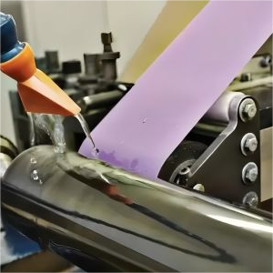
Roller finishing
-
Electronics
-
Semiconductors
-
Aerospace
-
Optical Glass Crystal
-
Jewellery lapidary
-

Medical
-

Oil & Gas
-
Food Processing
-
Furniture and Wood industry
-
Metals Finish
-
Fiber Optics Polishing
-
Music industry
-
LED LCD Panel
-
Mobile Phone Industry
-
Watch
-
Printing and Paper industry
-
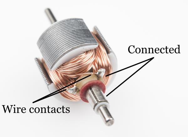
Engine and Machine parts
-
Hydraulic components
-
Pneumatic components
-
Ball bearings
-
Gear and Train components
-
Moulds
-
Cranks Cams and Steering devices
-

Dental Polishing
-
Knife Blade Tools sharpening
-
Hard disks and Magnetic head
-
Other parts end face polishing


